Custom UI
Introduction
The built-in menus of VIA (Keymap, Layouts, Macros, Save + Load) will be displayed depending on keyboard definition and firmware.
The menus element adds menus to VIA. It can contain one or more of the following built-in UI definitions:
and/or a definition of custom UI, i.e. explicitly defining all the UI controls required.
For example, a definition enabling the built-in UI for QMK RGB Matrix could be done like so:
"menus": ["qmk_rgb_matrix" ]
or alternatively defined explicitly using custom UI definitions, like so:
...
"menus": [
  {
    "label": "Lighting",
    "content": [
      {
        "label": "Backlight",
        "content": [
          {
            "label": "Brightness",
            "type": "range",
            "options": [0, 255],
            "content": ["id_qmk_rgb_matrix_brightness", 3, 1]
          },
          ...
        ]
      }
    ]
  }
]
The "qmk_backlight", "qmk_rgblight", "qmk_rgb_matrix", "qmk_backlight_rgblight" and "qmk_audio" strings enable the built-in UI definitions that match the default implementation of VIA protocol handlers in QMK, with respect to channel_id, value_id, etc.
These built-in UI definitions are defined the same way as custom UI definitions (i.e. JSON format). They can be used as examples to create custom UI definitions.
Definitions containing multiple top level menus with the same name (e.g. Lighting) will not merge into one top level menu. Thus, combining "qmk_backlight" and "qmk_rgblight" will result in two top-level Lighting menus. Use "qmk_backlight_rgblight" instead.
Similarly, combining built-in UI definitions with custom UI that has the same top-level menu name will result in multiple top-level menus, not a merged one. If you want to combine a built-in UI like qmk_rgb_matrix with extra lighting sub-menus under a single Lighting top level menu, explicitly define all the UI controls using the built-in UI definition as the base.
Structure
A custom UI definition (as a child element of menus) consists of a single top-level menu element with label and content elements.
A top-level menu element must contain one or more sub-menu elements as an array in content.
Each sub-menu element consists of a label and content element, and must contain one or more UI control elements as an array in the content element.
Each UI control element must have label, type and content elements.
Thus the "tree" has a maximum depth of three: top-level menu, sub-menu and UI control, and the type of entity is inferred from the depth.
Top Level Menus and Sub-Menus
Each element in the menus element defines a top-level menu, either a built-in one or a custom defined one. When custom defined, label defines the name displayed in the top left menu of the VIA app, and content is an array of sub-menu elements.
The following example defines:
- a top level menu
Lightingwith sub-menusUnderglowandIndicators - a top level menu
Displaywith sub-menusGeneralandAdvanced
"menus": [
  {
    "label": "Lighting",
    "content": [
      {
        "label": "Underglow",
        ...
      },
      {
        "label": "Indicators",
        ...
      }
    ]
  },
  {
    "label": "Display",
    "content": [
      {
        "label": "General",
        ...
      },
      {
        "label": "Advanced",
          ...
      }
    ]
  }
]
VIA will then display Lighting and Display in the top left menu, and then display the sub-menus in the bottom left, like this:
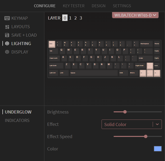
Note: Top-level menus should be consistent across all keyboards in VIA.
For example, all custom UI defined for any kind of lighting should use a top-level menu called Lighting, and then the sub-menus should be named with the specifics of that lighting, such as Underglow, Buttglow®, Backlight, Indicators.
Other top-level menus should be similarly generalized, such as Audio, Display, Knobs, etc.
Top-level menus are assigned an icon from keywords in the label. Labels containing light or rgb use a lighting icon; audio or sound use an audio icon; and display, oled, or lcd use a display icon. Other labels use a generic microchip icon.
In the case where a built-in definition requires some changes to match the firmware, the built-in definition can be inserted in place in the menus element and modified. In most cases, the default handlers in the firmware can be used.
Examples of this are:
- Replacing the sub-menu name
Underglowwith a different name - Configuring the set of lighting effects (e.g. changing the array of string/number pairs)
- Adding a new sub-menu and controls to match keyboard-level code which overrides the default behaviour (e.g. customized indicators)
This is facilitated by the use of channel_id in the set/get custom value commands. See Channel ID.
UI Controls
Definition
The sub-menu element has a content element, which is an array of UI control elements. Each UI control element must have label, type and content elements.
Example:
"menus": [
  {
    "label": "Lighting",
    "content": [
      {
        "label": "Underglow",
        "content": [
          {
            "label": "Brightness",
            "type": "range",
            "options": [0, 255],
            "content": ["id_qmk_rgblight_brightness", 2, 1]
          },
          {
            "label": "Effect",
            "type": "dropdown",
            "content": ["id_qmk_rgblight_effect", 2, 2],
            "options": [
              "All Off",
              "Solid Color",
              "Breathing 1",
              ...
            ]
          }
        ]
      }
    ]
  }
]
label defines the text label on the left of the control
type defines the type of control. Valid values are:
buttontogglerangedropdowncolorkeycodelabel
options defines the possible values of the control (the numerical range, or string/integer values)
content defines the binding of the control to the channel_id and value_id used in the VIA protocol. These values are preceded by a value_key string that is used by VIA. The value_key should match the name of the enum value in the firmware for uniqueness and readability. It must be unique for all UI controls in a UI definition.
The general command form is:
["value_key", channel_id, value_id, ...additional_arguments]
| Position | Meaning | Who defines it |
|---|---|---|
value_key | A unique string VIA uses to store, reference, and conditionally display the value. | Definition author |
channel_id | Routes the command to a feature handler. Custom keyboard values commonly use channel 0. | Fixed by built-in QMK features; otherwise chosen by the firmware author |
value_id | Identifies the value within that channel. | Fixed by built-in QMK features; otherwise chosen by the firmware author |
additional_arguments | Optional addressing bytes such as an array index, layer, or slot. | Firmware author |
Additional numeric arguments are optional. VIA preserves them when reading or writing the control and appends the new value after them for set commands. This supports array indexes, layers, or other firmware-defined addressing values.
For example:
{
  "label": "Brightness",
  "type": "range",
  "options": [0, 255],
  "content": ["id_qmk_rgblight_brightness", 2, 1]
}
... defines a range (slider) UI control, labelled Brightness, with a range of 0 to 255. It will be using channel_id of 2 and value_id of 1 in the VIA protocol to set/get the value in the firmware. It has a value_key of "id_qmk_rgblight_brightness" because the value_id of 1 matches the integer value of id_qmk_rgblight_brightness in enum id_qmk_rgblight in the firmware code.
Button Control
The button control is a clickable that sends a numeric value.

{
  "label": "Test button",
  "type": "button",
  "options": [10],
  "content": ["id_test_button", 0, 3]
}
The options element defines value to be sent, e.g. "options": [10],. The value data is one byte (i.e. <=255), otherwise it is two bytes. See Handling 16-bit Values for handling two byte values.
Toggle Control
The toggle control is a toggle switch that controls a boolean (on/off) value.

{
  "label": "God Mode",
  "type": "toggle",
  "content": ["id_god_mode", 0, 1]
}
The default value data is one byte, either 0 or 1. The options element can be used to define the two values if required, using an array of two values.
Range Control
The range control is a slider that controls a numeric value. The options element defines the range limits, e.g. "options": [0, 255],. The value data is one byte if the range maximum can fit in one byte (i.e. <=255), otherwise it is two bytes. See Handling 16-bit Values for handling two byte values.

{
  "label": "Audacity",
  "type": "range",
  "options": [0, 255],
  "content": ["id_audacity", 0, 2]
}
Relational constraints
A range can constrain its value relative to another range. This is useful for paired values such as press and release thresholds that must maintain an ordering or minimum gap.
{
  "label": "Actuation",
  "type": "range",
  "options": [0, 255],
  "content": ["id_actuation", 0, 10],
  "constraints": [
    {
      "operator": ">=",
      "reference": "id_release",
      "offset": 5,
      "onViolation": "push"
    }
  ]
}
Each constraint supports:
operator:<,<=,>, or>=reference: the other range'svalue_key, or its complete command tupleoffset: an optional positive or negative integer added to the referenced valueonViolation:clamporpush; the default isclamp
clamp stops the value at the closest valid boundary. push first moves the referenced control to preserve the relationship; if that control reaches its own bounds, the manipulated value is clamped instead.
Multiple constraints may be placed on one range. Constraints work with both one-byte and two-byte range values. VIA validates that referenced controls exist, full command references match their declaration, offsets are integers, and the declared ranges can satisfy the relationship.
Dropdown Control
The dropdown control is a drop-down menu of strings, which maps to an integer value. The options element defines the item labels and associated number.

{
  "label": "Date Format",
  "type": "dropdown",
  "options": [
    ["yyyy-mm-dd", 0],
    ["dd/mm/yyyy", 1],
    ["mm/dd/yyyy", 2]
  ],
  "content": ["id_date_format", 0, 5]
}
The numbers can be omitted from options, in which case, the array is of strings and the numbers implicitly assigned starting at zero, for example:
"options": [
  "yyyy-mm-dd",
  "dd/mm/yyyy",
  "mm/dd/yyyy"
]
This allows easier definition of things like lighting effects, which can be conditionally enabled. Firmware authors can copy the full set of strings from the built-in UI definition and edit it to match the firmware, without needing to define the numbers.
Color Control
The color control is a swatch of color showing the current color value, which pops up a color picker when clicked. It allows selection of hue and saturation values only, since brightness is usually controlled separately in lighting code.
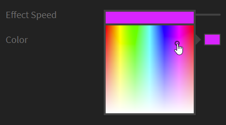
{
  "label": "Color",
  "type": "color",
  "content": ["id_qmk_rgblight_color", 2, 4]
}
Keycode Control
The keycode control allows display and editing of a QMK keycode. Firmware writers can use this for custom rotary encoder handling or any other way of triggering keycode events.

{
  "label": "Head Slam",
  "type": "keycode",
  "content": ["id_head_slam", 0, 6]
}
Keycodes are 16-bit values, so the value data is two bytes. See Handling 16-bit Values
Static and Keyboard-Provided Display Labels
The label type displays read-only text using the same value styling as a range control. It supports two content forms.
Static label
A one-element content array contains the text directly in the definition. VIA displays it without issuing a custom-value command:
{
  "label": "Information",
  "type": "label",
  "content": ["Device is ready"]
}
Keyboard-provided label
A custom-value command tuple tells VIA to read dynamic text from the keyboard:
{
  "label": "Board status",
  "type": "label",
  "content": ["id_board_status", 0, 2]
}
The tuple has the same structure as other custom controls: [value_key, channel_id, value_id, ...arguments]. The keyboard must return null-terminated UTF-8 bytes in the custom-value response. This form is reread when VIA refreshes the matching value, including after a board-initiated synchronization request.
Both forms are display-only and do not send set or save commands.

Showing/Hiding Controls
Sometimes good UI design requires only showing a control when another control is in a given state. For example, a dropdown control for a "mode" and only showing controls which are used in that "mode".
The showIf element can be used to show one (or more) UI controls only if the expression evaluates true.
The built-in UI for qmk_rgblight shows an example of showIf. The Effect Speed and Color are only shown for some Effect values. Note how the value of a dropdown control evaluates to the number value of the string/number pair.
Example:
{
  "label": "Effect",
  "type": "dropdown",
  "content": ["id_qmk_rgblight_effect", 2, 2],
  "options": [
    "All Off",
    "Solid Color",
    "Breathing 1",
    "Breathing 2",
    "Breathing 3",
    "Breathing 4",
    ...
  ]
},
{
  "showIf": "{id_qmk_rgblight_effect} >= 2",
  "label": "Effect Speed",
  "type": "range",
  "options": [0, 3],
  "content": ["id_qmk_rgblight_effect_speed", 2, 3]
},
{
  "showIf": "{id_qmk_rgblight_effect} > 0",
  "label": "Color",
  "type": "color",
  "content": ["id_qmk_rgblight_color", 2, 4]
}
Alternatively, the showIf element can "contain" one or more UI controls, which are only shown if the expression evaluates true.
For example, the following will only display the Audacity and Tenacity range controls if the God Mode toggle is on.
{
  "label": "God Mode",
  "type": "toggle",
  "content": ["id_god_mode", 0, 1]
},
{
  "showIf": "{id_god_mode} == 1",
  "content": [
    {
      "label": "Audacity",
      "type": "range",
      "options": [0, 255],
      "content": ["id_audacity", 0, 2]
    },
    {
        "label": "Tenacity",
        "type": "range",
        "options": [0, 255],
        "content": ["id_tenacity", 0, 3]
    }
  ]
}
...
The expression evaluator uses operators such as ==, !=, <, <=, >, >=, ||, &&, !, (, ). Values are referenced by enclosing their key string in { and }.
Firmware-version conditions
VIA also exposes the keyboard's 32-bit VIA_FIRMWARE_VERSION as id_firmware_version while evaluating V3 custom UI:
{
  "showIf": "{id_firmware_version} >= 5",
  "label": "New firmware feature",
  "type": "toggle",
  "content": ["id_new_feature", 0, 24]
}
The condition can be placed on an individual item, a conditional group, a submenu, or a top-level menu.
- Hidden items and groups are not rendered.
- A firmware-gated submenu remains listed but disabled and explains that the feature is unavailable for the connected firmware.
- A top-level menu remains available and shows an unavailable-features message when its condition is false.
VIA does not read commands from a branch whose condition refers only to id_firmware_version and evaluates false. This allows mutually exclusive firmware branches to reuse a value_key or numeric command ID safely. Keep definitions for every supported firmware generation in the JSON, and place the version condition high enough to cover every command whose meaning changed.
Define the reported value in the VIA keymap's config.h:
#define VIA_FIRMWARE_VERSION 5
The top-level JSON firmwareVersion property is not a substitute for conditional controls; current VIA uses the version reported by the connected firmware when evaluating showIf.
Array Values
Sometimes firmware has a set of the same type of values, for which enumerating each in an enum, and using a range of value_id values, is not elegant.
In this situation, one or more numbers can be added after the value_id in the content element. These can be used for any purpose in the firmware, such as an index into an array.
Example:
"content": ["id_some_value_array[0]", 9, 99, 0]
For example, to control 3 color values, rather than defining 3 enum values in firmware, a single enum value id_buttglow_color can be used, a single integer value used for value_id, and a value index appended in the UI control definition, as follows:
{
  "label": "Color 1",
  "type": "color",
  "content": ["id_buttglow_color[0]", 0, 4, 0]
},
{
  "label": "Color 2",
  "type": "color",
  "content": ["id_buttglow_color[1]", 0, 4, 1]
},
{
  "label": "Color 3",
  "type": "color",
  "content": ["id_buttglow_color[2]", 0, 4, 2]
}
Note that the value_key (the string in content) must be unique per UI control, so for array values, include the array index in the string.
Firmware Implementation
Custom UI is handled in firmware by handling three commands of the VIA protocol:
id_custom_set_valueid_custom_get_valueid_custom_save
When enabling VIA and a feature (like lighting) in QMK Core, by default, the command handlers that match the built-in UI definitions will be compiled. Firmware authors who do not add or extend a feature do not need to write handlers of the above commands.
The following describes how to implement handlers for the above commands, in keyboard level code, to match the custom UI definitions in VIA.
Channel ID
id_custom_set_value and id_custom_get_value commands use a channel_id for routing commands to handlers for that feature, and a value_id to identify the value.
channel_id is a qualifier to value_id, allowing multiple enums with overlapping integer ranges to be used, rather than a single enum that must be the superset of all values for all features.
The built-in UI definitions use channel_id values that match the default values in firmware. When using custom UI definitions, the channel_id values can be defined to anything on both sides (QMK and VIA).
id_custom_save command uses a channel_id to signal saving the current state of values associated with that channel. See Saving Values
Value ID
When implementing a new feature, either in QMK Core or at the keyboard level, define a new enum for the possible value_id values, explicitly assigning integer values starting with 1.
For example:
enum via_buttglow_value {
    id_buttglow_brightness   = 1,
    id_buttglow_effect       = 2,
    id_buttglow_effect_speed = 3,
    id_buttglow_color        = 4
};
Command Handlers
via_custom_value_command() (in via.c) has the default handling of custom value commands for QMK Core modules like lighting. It will use the channel_id to route the commands to handlers specific to that feature. If the channel_id in the command does not match the channels it is enabled to handle, it will call via_custom_value_command_kb(), allowing keyboard level code to handle the commands for that channel_id.
Thus, overriding via_custom_value_command_kb() in the keyboard level code allows firmware authors to write a command handler to set/get the values defined by the custom UI definition in VIA.
In the simple case of implementing a few keyboard specific custom values, it is recommended to use a channel_id of id_custom_channel = 0, which won't conflict with the channels being handled in via.c, as these start with 1. However, firmware authors could choose to use multiple channel_id values, to support multiple features.
IDs on custom channel
0are defined by the keyboard author. The numericvalue_idin a JSONcontenttuple must match the keyboard's custom enum, but it is not assigned or reserved by VIA. This applies equally to custom-menu controls, firmware-backed labels, and dynamic keyboard names. The numbers used throughout this documentation are examples. Built-in QMK menus are different because their channel and value IDs must match the fixed handlers in QMK and VIA.
It is possible to combine the default command handlers for a QMK feature (using the default channel_id) with a command handler for a keyboard specific feature. For example, a firmware author could use the built-in UI for RGB Matrix on channel id_qmk_rgb_matrix_channel = 4, and implement via_custom_value_command_kb() to only handle commands on channel id_custom_channel = 0.
In the rare case of needing to subvert/extend/replace the default custom value handling of a QMK feature, via_custom_value_command() itself can be overridden and reimplemented in keyboard level code, handling the channel_id for QMK features.
The following is an example of implementing via_custom_value_command_kb(). It routes the three commands to functions to handle each command, this avoids nested switch/case statements and improves readability.
void via_custom_value_command_kb(uint8_t *data, uint8_t length) {
    // data = [ command_id, channel_id, value_id, value_data ]
    uint8_t *command_id        = &(data[0]);
    uint8_t *channel_id        = &(data[1]);
    uint8_t *value_id_and_data = &(data[2]);

    if ( *channel_id == id_custom_channel ) {
        switch ( *command_id )
        {
            case id_custom_set_value:
            {
                buttglow_config_set_value(value_id_and_data);
                break;
            }
            case id_custom_get_value:
            {
                buttglow_config_get_value(value_id_and_data);
                break;
            }
            case id_custom_save:
            {
                buttglow_config_save();
                break;
            }
            default:
            {
                // Unhandled message.
                *command_id = id_unhandled;
                break;
            }
        }
        return;
    }

    // Return the unhandled state
    *command_id = id_unhandled;

    // DO NOT call raw_hid_send(data,length) here, let caller do this
}
The following is an example of implementing the set/get command handlers specific to a feature - switch on possible values and set/get the values to/from a global struct which stores the state being used by the feature. Triggering update functions on state change can be optionally added.
void buttglow_config_set_value( uint8_t *data )
{
    // data = [ value_id, value_data ]
    uint8_t *value_id   = &(data[0]);
    uint8_t *value_data = &(data[1]);

    switch ( *value_id )
    {
        case id_buttglow_brightness:
        {
            g_buttglow_config.brightness = *value_data;
            break;
        }
        ...
    }
}

void buttglow_config_get_value( uint8_t *data )
{
    // data = [ value_id, value_data ]
    uint8_t *value_id   = &(data[0]);
    uint8_t *value_data = &(data[1]);

    switch ( *value_id )
    {
        case id_buttglow_brightness:
        {
            *value_data = g_buttglow_config.brightness;
            break;
        }
        ...
    }
}

void buttglow_config_save(void)
{
    eeprom_update_block( &g_buttglow_config,
        ((void*)BUTTGLOW_CONFIG_EEPROM_ADDR),
        sizeof(buttglow_config) );
}
Saving Values
The id_custom_save command is sent after one or more id_custom_set_value commands have been sent, and after a small delay. It is used to allow the firmware to defer writing to EEPROM and respond to set value commands quickly. This also reduces the number of redundant writes to EEPROM, especially when users are changing values quickly in VIA, like when using a color picker. The channel_id of the id_custom_save command will be the same value as used in the preceding id_custom_set_value commands, allowing a handler to save all current values for a feature by channel.
Handling 16-bit Values
The keycode control will send/receive 16-bit values. Likewise, the range control will send/receive 16-bit values if the range maximum is greater than 255. The order of bytes is [high byte, low byte].
In the following example, g_buttglow_config.audacity is uint16_t and the range control is configured to use a range of 0 to 1023.
void buttglow_config_set_value( uint8_t *data )
{
    // data = [ value_id, value_data ]
    uint8_t *value_id   = &(data[0]);
    uint8_t *value_data = &(data[1]);

    switch ( *value_id )
    {
        case id_buttglow_audacity:
        {
            g_buttglow_config.audacity = value_data[0] << 8 | value_data[1];
            break;
        }
        ...
    }
}

void buttglow_config_get_value( uint8_t *data )
{
    // data = [ value_id, value_data ]
    uint8_t *value_id   = &(data[0]);
    uint8_t *value_data = &(data[1]);

    switch ( *value_id )
    {
        case id_buttglow_audacity:
        {
            value_data[0] = g_buttglow_config.audacity >> 8;
            value_data[1] = g_buttglow_config.audacity & 0xFF;
            break;
        }
        ...
    }
}
Handling Array Values
The following is an example of a custom UI control using an array value, the array index is after the value_id, thus it is in value_data[0] and the actual value starts at value_data[1], whereas for non-array values, the value starts at value_data[0].
void buttglow_config_set_value( uint8_t *data )
{
    // data = [ value_id, value_data ]
    uint8_t *value_id = &(data[0]);
    uint8_t *value_data = &(data[1]);

    switch ( *value_id )
    {
        case id_buttglow_color: // == 4
        {
            uint8_t index = value_data[0]; // == 0,1,2
            if ( index >= 0 && index < 3 )
            {
                g_buttglow_config.color[index].h = value_data[1];
                g_buttglow_config.color[index].s = value_data[2];
            }
        }
        ...
    }
}
See Array Values
Board-Initiated Custom UI Synchronization
Normally VIA reads custom-menu values when a keyboard connects and after a value is changed through the app. Firmware can also request a refresh when a value changes independently, such as after a board task completes or a hardware mode switch changes state.
The synchronization flow is:
- The board changes one or more values independently of VIA.
- Firmware queues a full or targeted synchronization request.
- Firmware sends the request after the current VIA receive handler has returned.
- VIA waits for active HID commands, coalesces requests, and rereads the matching active controls.
The firmware sends a versioned UI_SYNC_REQUEST report (0x16) through the existing VIA Raw HID interface. Version 0x01 supports three request types:
| Type | Value | Payload |
|---|---|---|
| Refresh all custom values | 0x00 | No targets |
| Refresh channel/command pairs | 0x01 | Two bytes per target: channel ID, command ID |
| Refresh command IDs | 0x02 | One command ID per target |
The report begins with:
[0x16, version, type, count, ...targets]
For example, this report asks VIA to refresh the author-defined command IDs 2 and 3 regardless of channel:
uint8_t report[RAW_EPSIZE] = {0};
report[0] = 0x16; // UI_SYNC_REQUEST
report[1] = 0x01; // request format version
report[2] = 0x02; // command-ID targets
report[3] = 2;    // target count
report[4] = 2;
report[5] = 3;
raw_hid_send(report, sizeof(report));
Send synchronization reports outside the VIA receive handler—for example, from housekeeping_task_user() after a short delay. This avoids sending a second Raw HID report while VIA is still processing the command that caused the change.
Firmware implementations should coalesce pending requests, remove duplicate targets, keep the payload within RAW_EPSIZE, and send only from the master side of a split keyboard. A refresh-all request should take precedence over a pending selective refresh.
VIA queues and coalesces requests for each device, waits for active HID commands to finish, and merges only the requested values into the current UI state. Unsupported request versions and types, and targets absent from the active definition, are ignored.
A paired definition and deferred QMK implementation is available in Board-initiated UI synchronization.